What is Reverse Engineering?
Reverse Engineering is the practice of taking an existing part, whether working, broken or worn-out, and either replicating an exact duplicate, or modifying it to fit another need. Traditionally, reverse engineering of complex parts requires painstaking measurements using a myriad of calibers, micrometer and/or CMM machines. In many instances, the part must be physically cut into cross sections in order to get accurate measurements along complex surfaces. This obviously is very difficult, time consuming, and destroys the part! Utilizing a quality 3D scan is a much more efficient way to produce a CAD file from a physical object, especially one with complex or freeform geometry.
Reverse Engineering Models Types
Surface “Shrink-wrapped” Model
Surface models are used when exact replicas are needed. Freeform shapes such as bones, sculptures and custom fit molds are excellent candidates for surface modeling. They are a universal file format, so they can be used in almost all 3D CAD software. However, they do have their limitations. Because they are exact replicas of the original part, they will show all of the manufacturing defects, worn or bent areas of the model. They are much harder to modify at a later date. Because they are the quickest and easiest type of model to produce, they are usually the cheapest to produce.
Solid Model
Solid models are used in engineering or manufacturing applications when design intent is required, but further modification isn’t needed. Unlike shrink-wrapped models which must incorporate the defects in the scanned object, solid models can be designed to ignore defects and recreate perfect geometric shapes. They are often called “Dumb Solids” because although they are constructed using traditional parametric modeling tools, they are exported in universal file formats that cannot be edited by the end user in traditional 3D CAD software.
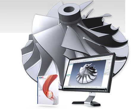
Parametric Model
A full parametric model is the “gold standard” type of model for almost all types of engineering or manufacturing. Like other solid models, parametric models are created using traditional parametric tools, such as extrusions, lofts, geometric shapes and splines. The difference is that unlike a “dumb solid”, a parametric model is exported into most 3D modelers native format. This is a much more involved and time consuming process, but the end result is that you have a full history based native file. With the use of a feature tree, the model can be remodeled and changed or adapted in the future with minimal effort. If a fully featured and adaptable model is what you need, then a native parametric model is the best choice.